TM 5-5420-280-23&P
0112 00
VALVE CLEARANCE MAINTENANCE (Contd)
CAUTION
Clean all dust, dirt, or other foreign material from around cylinder
heads and valve covers before removing valve covers. Failure to
comply may result in damage to equipment.
COVER REMOVAL
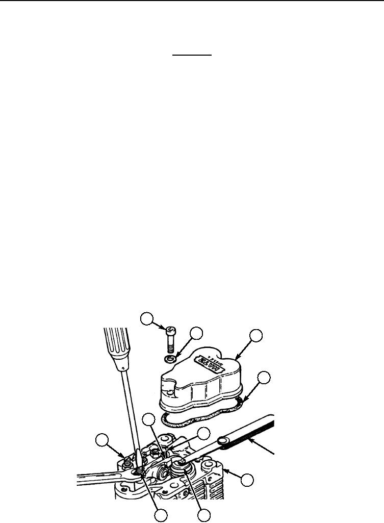
Remove four screws (1), sealing rings (2), two valve covers (3), and cover gaskets (4) from cylinder
heads (6). Discard sealing rings (2) and valve cover gaskets (4).
VALVE ADJUSTMENT
NOTE
Only adjust valves on a cold 5086F (1030C) engine.
No. 1 cylinder is at the flywheel end of the engine and No. 2
cylinder is at the power takeoff end. Only one cylinder head is
shown.
1.
Rotate engine flywheel in its normal direction of rotation until valves (5) and (7) on cylinder No. 2
are in overlap position, exhaust valve (7) is not yet closed and intake valve (5) is starting to open.
2.
Rotate flywheel 180 degrees in normal direction and check valve clearance on No. 1 cylinder using a
.025 in. (0.10 mm) feeler gauge. If necessary, perform step 4.
3.
Rotate flywheel 180 degrees more and check valve clearance on No. 2 cylinder using a .025 in.
(0.10 mm) feeler gauge. If necessary, perform step 4.
4.
If adjustment is necessary, loosen nut (8) and turn screw (9) until .025 in. (0.10 mm) feeler gauge
will just pull through between valve stem and rocker arm (10) and tighten nut (8). Recheck
clearance and adjust if necessary.
COVER INSTALLATION
Install two new cover gaskets (4) and valve covers (3) on cylinder heads (6) with four new sealing
rings (2) and screws (1).
1
2
3
4
10
5
9
FEELER GAUGE
6
7
8
END OF WORK PACKAGE
0112 00-2

