
TM 5-5420-280-23&P
0118 00
TORQUE LIMITS (Contd)
TUBING APPLICATION TIGHTENING ASSEMBLY INSTRUCTIONS (Contd)
COPPER TUBING
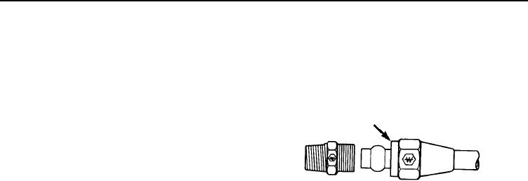
1. Slide nut and then sleeve on tubing. Threaded
FOR HAND AIRBRAKE
end of nut (B) must face out.
2. Insert tubing into fitting. Ensure tubing is
B
bottomed on fitting shoulder.
3. Thread nut onto fitting body until it is hand
tight.
4. From that point, tighten with a wrench the
number of turns indicated at right.
TUBE
ADDITIONAL NUMBER
SIZE
OF TURNS FROM HAND TIGHT
1-3/4
1-3/4
3-1/4
3-1/4
TORQUE WRENCH ADAPTERS
Some maintenance tasks require the use of a torque wrench adapter when the nut or screw cannot be
reached with a regular socket on the end of the torque wrench. These adapters add to the overall length of
the torque wrench and make the dial or scale reading less than the actual torque applied to the nut or
screw. To prevent overtightening and damage to equipment, calculate the correct dial or scale reading using
the conversion formula provided; refer to Conversion Formula in this WP.
0118 00-6