
TM 5-5420-226-20-3
PARKING BRAKE CONTROL ASSEMBLY AND LINKAGE REPLACEMENT (Sheet 11 of 17)
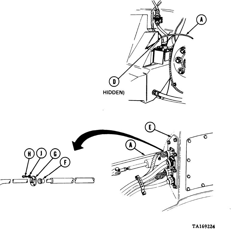
With one person inside compartment at commander's position palling wire extending
5.
from bulkhead, second person carefully threads control assembly (A) through tube (D)
located behind fuel tank until control assembly (A) end is visible at bulkhead (E) inside
compartment.
Continue to pull control assembly (A)
6.
through bulkhead (E) until black grease
pencil reference mark is at bulkhead
wall location.
Position new split bushing (F) over control
7.
assembly (A) with sealing compound.
Allow 20 minutes to dry, then put bushing
(F) into bulkhead (E).
Slide retainer (G) onto control assembly (A).
8.
Using screwdriver, install retainer (G) to
bulkhead (E) with four screws (H) and
lockwashers (J).
Go on to Sheet 12
13-100

