
TM 5-5420-226-20-3
STEERING CONTROL LINKAGE ADJUSTMENT (Sheet 4 of 22)
7.
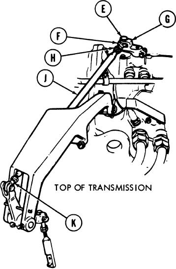
Using 9/16 inch wrench to hold steering
rod end (F), use 9/16 inch wrench to
loosen jamnut (H).
8.
Using 9/16 inch wrench, adjust length of
control rod (J) by turning steering rod end
(F) clockwise or counterclockwise until
screw (E) drops freely through clevis (G)
and steering rod end (F).
Using small gage wire, check to see if
9.
control rod (J) is into steering rod ends (F)
and (K) past witness holes. If control rod
(J) is past witness holes in both steering
rod ends (F) and (K), go on to step 24. If
control rod (J) is not past witness hole in
steering rod end (K), go on to step 20. If
control rod (J) is not past witness hole in
steering rod end (F), go on to step 10.
10.
Using 9/16 inch wrench, turn steering rod end (F) clockwise until control rod (J) is
just past witness hole in steering rod end (F).
11.
Using 9/16 inch wrench to hold steering rod end (F), use 9/16 inch wrench to tighten
jamnut (H).
TA169394
Go on to Sheet 5
15-34

