
TM 5-5420-228-24
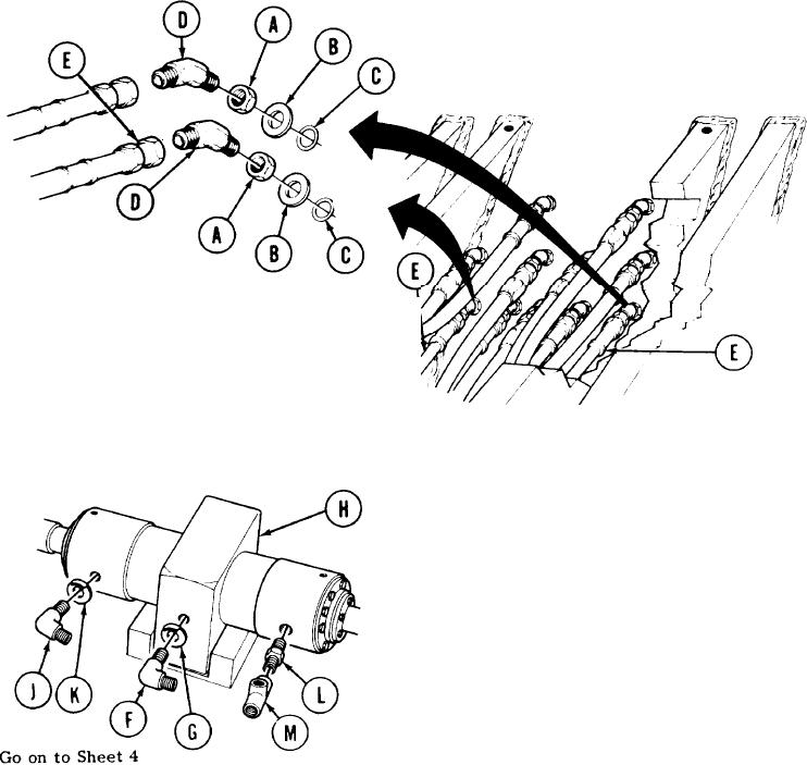
LOCKING CYLINDER HOSE ASSEMBLIES (CE1, CE2, AND M) AND HYDRAULICS REPLACEMENT
(Sheet 3 of 4)
INSTALLATION:
NOTE
Before installation, use pipe tape on all male
threads. Start tape on second thread so tape
will not enter hydraulic system.
Manually install nuts (A), flat washers (B), and new preformed packings (C) on elbows (D).
1.
Install and aline two elbows (D) in vehicle as shown.
2.
3.
Using 3/4 inch wrench to hold elbows (D),
use 7/8 inch wrench to tighten elbow nuts
(A).
Holding elbows (D) with 3/4 inch wrench
4.
use 7/8 inch wrench to install hose
assemblies "CE1" and "CE2" (E).
Using adjustable wrench, install elbow (F)
5.
and collar "CE2" (G) in middle port Of
locking cylinder (H).
Using adjustable wrench, install elbow (J)
6.
and collar "M" (K) in right port of locking
cylinder (H).
Using 3/4 inch wrench, install nipple
7.
(L) in left port of locking cylinder
(H).
Holding nipple (L) with 3/4 inch wrench,
8.
use adjustable wrench to install tee
(M) on nipple (L).
TA251551
3-153

