
T M 5-5420-228-24
RESERVOIR-TO-PUMP HOSE ASSEMBLY (CV5) REPLACEMENT (Sheet 1 of 3)
7/8 in. open end wrench
TOOLS:
1-1/8 in. open end wrench
1-7/16 in. open end wrench
1-3/4 in. open end wrench
12 in. adjustable wrench
Pipe tape (Item 19, Appendix D)
SUPPLIES:
Drip pans (suit able containers)
Rags (Item 12, Appendix D)
Masking tape (Item 18, Appendix D)
Pencil (Item 22, Appendix D)
LO 5-5420-202-12
REFERENCE:
Drain hydraulic reservoir (page 3-74)
PRELIMINARY
PROCEDURE:
REMOVAL:
NOTE
Use drip pan and rags to catch hydraulic
fluid trapped in lines. Use masking tape to
tag lines for installation.
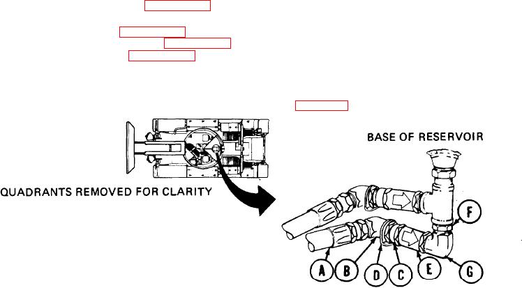
1.
Using 7/8 inch wrench, disconnect hose
assembly "CV5" (A) from elbow (B).
Using 1-1/8 inch wrench to hold bushing (C), use adjustable wrench to remove elbow
2.
(B) and collar (D).
Using 1-7/16 inch wrench to hold check valve (E), use 1-1/8 inch wrench to remove bushing
3.
(c).
Using 1-7/16 inch wrench, remove check valve (E).
4.
Using 1-3/4 inch wrench to hold bushing (F), use adjustable wrench to remove elbow
5.
(G).
Go on to Sheet 2
TA251590

