
TM 5-5420-280-23&P
0081 00
HYDRAULIC SUPPORTING WHEELS CONTROL VALVE, SELECTOR VALVE, PRESSURE REGULATOR
VALVE, PRESSURE GAUGE, AND PUMP REPLACEMENT (Contd)
PUMP AND PRESSURE GAUGE INSTALLATION (Contd)
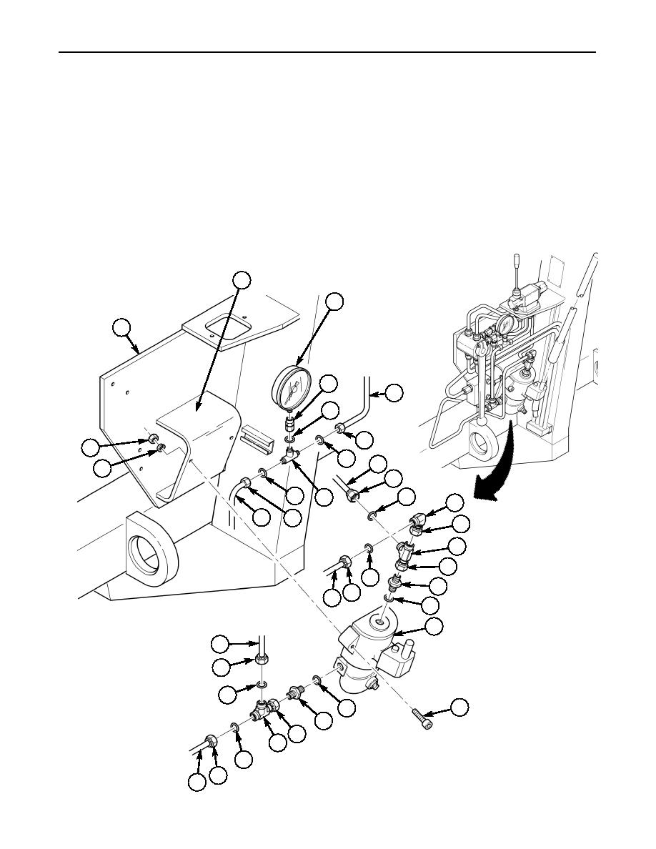
10.
Install new O-ring (5), reducer (4), and pressure gauge (3) on tee fitting (28).
11.
Install two new tube seals (9) and tubing (30) and (6) on tee fitting (28) with pressure gauge (3)
attached and tighten nuts (29) and (27).
NOTE
The pallet hydraulic system is self-bleeding, and with the exception
of the telescopic tube hydraulic cylinders, there is no requirement
for bleeding air from the system.
12.
Operate hydraulic supporting wheels and check for leaks. Refer to TM 5-5420-280-10.
2
3
1
4
6
~
5
27
32
9
7
31
8
9
9
28
10
30
29
11
12
13
9
14
26 25
15
16
24
23
9
17
15
18
19
20
9
21
22
END OF WORK PACKAGE
0081 00-9/10 blank

