
TM 5-1940-322-24
0167 00
HYDROJET ASSEMBLY REPAIR (Contd)
DISASSEMBLY
1.
Place hydrojet assembly (1) on suitable blocks to support intake housing (2) during disassembly.
2.
Remove four locknuts (22), washers (23), insulator washers (24), and hydrojet nozzle (19) from tailpipe
housing (12). Discard locknuts (22).
3.
Remove locknut (17), washer (18), and anode (16) from stud (15) on end cone (14). Discard locknut (17).
4.
Remove four locknuts (20), washers (21), and end cone (14) from tailpipe housing (12). Discard
locknuts (20).
5.
Remove three wing nuts (28) and inspection cover (29) with O-ring (34) from top of intake housing (2).
Install drive shaft support tool TD-321257 through inspection cover opening with carriage (33) around
impeller shaft (6).
6.
Install support plate (31) and wing nut (30) on rod (32). Adjust wing nut (30) to support impeller
shaft (6).
7.
Remove eight locknuts (25), washers (26), insulator washers (27), and tailpipe housing (12) with water
bearing (13) and gasket (9) from impeller shaft (6) and intake housing flange (7). Discard locknuts (25)
and gasket (9).
8.
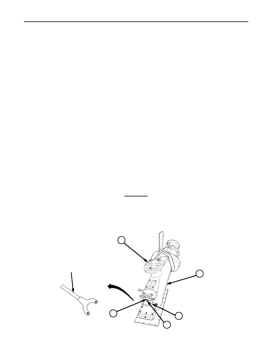
Install drive flange C-spanner tool TD-321256 on hydrojet flange (3) to keep impeller shaft (6) from
turning. Loosen locknuts (4) and (11) on hydrojet flange end of shaft (6) and impeller end of shaft (6).
Do not remove locknuts (4) and (11) or washers (5) and (10) from end of shaft (6).
9.
Remove locknut (11), washer (10), and shaft sleeve (8) from end of impeller shaft (6). Remove retaining
pin (36) from shaft (6) and install impeller removal tool set TD-120891 on end of shaft (6) as follows:
a. Install thrust pad (38) from set over threads of shaft (6).
b. Install draw tube (39) from set over shaft (6) with screw (40) backed out.
c. Install three screws (41) from set through end of draw tube (39) and into end of impeller
hub (42), tighten screws (41) until end of draw tube (39) is tight against impeller hub (42).
CAUTION
When removing impeller from shaft, do not twist impeller on shaft.
Failure to comply may result in damage to shaft or impeller.
10.
Tighten screw (40) from set on of draw tube (39) and remove impeller (37) from key (35), cone (43),
and impeller shaft (6). Remove key (35) and cone (43) from impeller shaft (6). Remove three
screws (41) and draw tube (39) from impeller hub (42).
1
DRIVE FLANGE
C-SPANNER TOOL
TD-321256
2
5
3
4
0167 00-2
