TM 5-5420-202-20-2
FUEL-WATER SEPARATOR OPERATIONAL TESTS (Sheet 2 of 11)
Manual Drain Test (Sheet 1 of 2)
NOTE
In order to perform any of the tests in this proce-
dure, they must be performed in the sequence
listed.
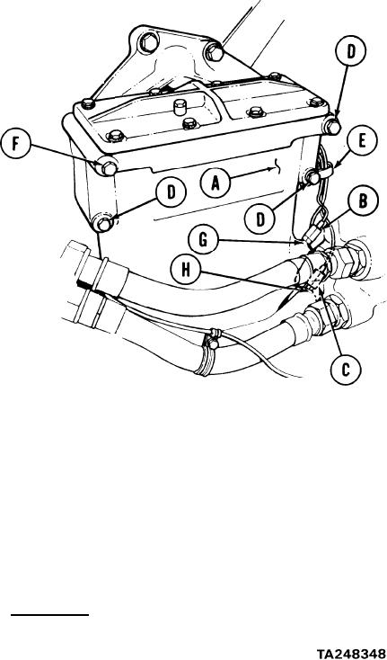
Place drip pan under fuel-water separator (A) and sensors (B) and (C).
1.
Using 1/2 inch socket and extension, remove three capscrews, lockwashers,
2.
and washers (D).
3.
Using hands, remove clamp (E) from sensor
wires (B) and (C).
Using 1/2 inch socket and extension, loosen
4.
c a p s c r e w (F) to provide movement of fuel-water
separator.
NOTE
It may be necessary to use hammer and punch to
unseat sensors (B) and (C) by tapping upward
on the edge of the sensor retaining nut.
5.
Using 1/2 inch wrench to hold sensor retaining
nut (G), use 9/16 inch wrench and remove upper
sensor (B) from fuel-water separator.
NOTE
Check to see if fluid level is above upper sensor (B) hole by noting
leakage when upper sensor (B) is removed.
6.
Tag upper sensor (B) to make sure of correct installation.
Using 1/2 inch wrench, remove sensor retaining nut (G).
7.
Using 5/16 inch wrench, install pipe plug into upper sensor (B) hole.
8.
Using 1/2 inch wrench to hold sensor retaining nut (H), use 9/16 inch wrench and
9.
remove lower sensor (C) from fuel-water separator.
Tag lower sensor (C) to make sure of correct installation.
10.
11.
Using 1/2 inch wrench, remove sensor retaining nut (H).
12.
Using 5/16 inch wrench, install pipe plug into lower sensor (C) hole.
CAUTION
Be very careful not to disturb center filter element.
The center filter element must be replaced if disturbed
Go on to Sheet 3
in any way.
7-224

