
TM 5-5420-202-20-3
MASTER CONTROL PANEL REPAIR (Sheet 8 of 73)
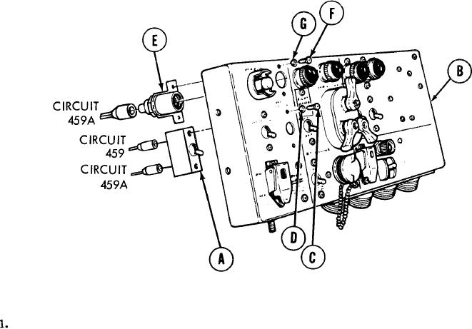
Master Battery Switch And Indicator Lamp Replacement (Sheet 3 of 4)
INSTALLATION:
A p p l y silicone compound to two male connectors (circuits 459 and
459A).
2.
Using fingers, install two connectors (circuits 459 and 459A) to rear of switch (A) by
pushing in.
3.
Place switch (A) in position on panel (B).
4.
Using screwdriver, install two screws (C) and lockwashers (D).
5. Using fingers, install connector (circuit 459A) to rear of base assembly (E) by pushing
in.
6.
Place base assembly (E) in position on panel (B).
7.
Using screwdriver, install two screws (F) and lockwashers (G) securing base assembly
(E) to panel (B).
Go to Sheet 4
TA248986