
TM 5-5420-202-20-3
INSTRUMENT PANEL CLUSTER ASSEMBLY REPAIR (Sheet 7 of 23)
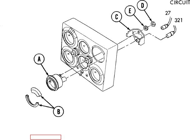
Transmission Oil Pressure Indicator Replacement (Sheet 2 of 2)
INSTALLATION:
1. Apply silicone compound to two indicator (A) electrical connectors.
2. Place bezel (B) in position on indicator (A).
3. Place indicator (A) and bezel (B) in position in panel.
4. Place mounting bracket (C) in position on indicator (A).
5. Using wrench, install two nuts (D) and lockwashers (E) securing indicator (A) and
mounting bracket (C) to panel.
6. Connect two leads (circuits 27 and 321) to rear of indicator (A) by pushing in.
7. Install panel in vehicle (page 10-112).
End of Task
TA249061
10-120