
TM 5-5420-202-20-3
BRAKE PRESSURE GAGE, TUBE ASSEMBLY, REDUCER, AND GASKET REPLACEMENT
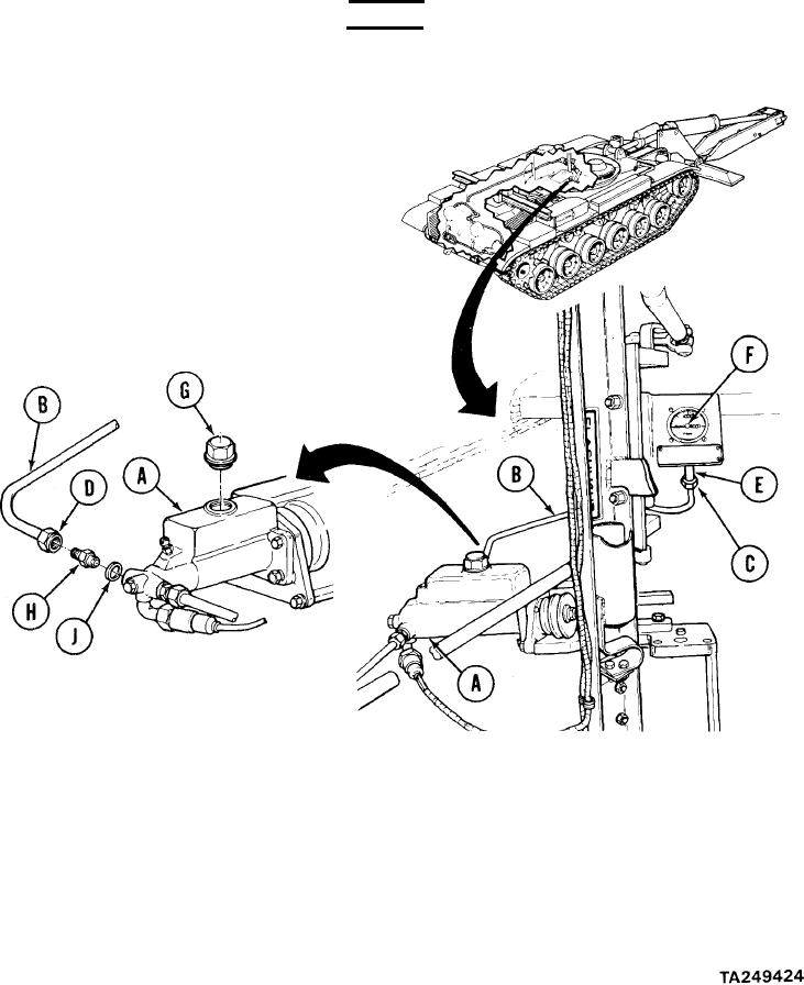
(Sheet 2 of 7)
REMOVAL:
WARNING
Cleaning agent specified is flammable. Use only in well ventilated areas. Keep away from flames,
sparks, or heat. Do not smoke while using. Prevent contact with eyes, mouth, and/or skin. Wear
rubber gloves when performing cleaning procedures.
1.
Using dry cleaning solvent and rags,
clean master cylinder (A), brake tube
(B), tube nuts (C) and (D), elbow (E),
and brake pressure gage as-
sembly (F).
2.
Using hands, place funnel and container
under tube nut (D) to catch
brake fluid.
Using 1-1/8 inch socket, remove filler
3.
cap (G) from master cylinder (A).
Using 3/4 inch wrench to hold reducer (H), use 9/16 inch wrench to remove tube nut (D).
4.
After brake fluid has drained from master cylinder (A), use fingers to install filler cap
5.
(G) to master cylinder.
Using 3/4 inch wrench, remove reducer (H) and gasket (J). Throw gasket (J) away. Plug
6.
hole with plastic plug.
Go on to Sheet 3
13-36