
TM 5-5420-202-20-3
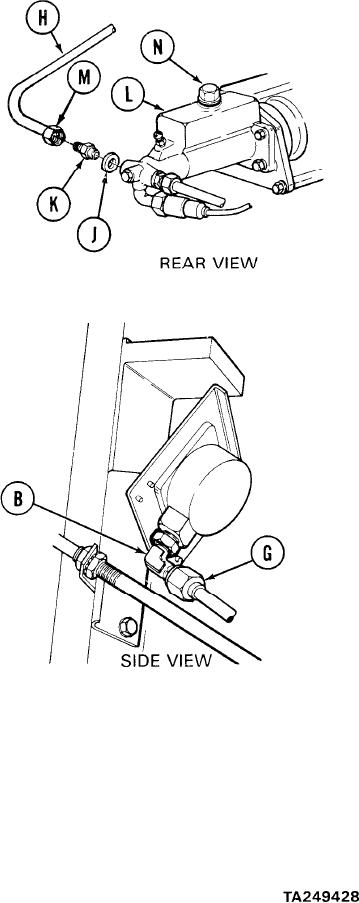
BRAKE PRESSURE GAGE, TUBE ASSEMBLY, REDUCER, AND GASKET REPLACEMENT
(Sheet 6 of 7)
8.
Using fingers, install gasket (J) to reducer
(K).
Using 3/4 inch wrench, install reducer (K) to
9.
master cylinder (L).
10.
Using 9/16 inch wrench, install tube
connecting nut (M) and brake tube assembly
(H) to reducer (K).
11.
Using fingers, remove filler cap (N) from
master cylinder (L).
12.
Using funnel, fill master cylinder with brake
fluid to 1/4 inch from top of opening.
13.
Using 1-1/8 inch socket, install filler
cap (N) to master cylinder (L).
14.
Using hands, place rags or container
under line connecting nut (G) to catch
brake fluid during line bleeding procedure.
Depress brake pedal until brake fluid appears running clear and free of bubbles at line
15.
nut (G).
16.
Using 9/16 inch wrench, tighten nut (G) while holding elbow (B) with 1/2 inch wrench.
Using 1-1/8 inch socket, remove filler cap (N).
17.
Fill master cylinder with brake fluid to 1/4 inch from top of opening and install filler
18.
cap (N).
Go on to Sheet 7
13-40