
TM 5-5420-202-20-3
TRACK SUPPORT ROLLER REPLACEMENT (Sheet 10 of 11)
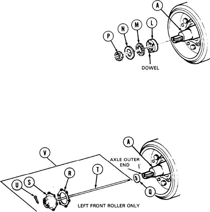
18. Install lock (M) and aline hole in lock (M) to
dowel of nut (L).
NOTE
If hole in lock (M) does not line up
to dowel of nut (L), turn lock over
for closer alinement.
19.
Install new nut lock (N) onto axle (A).
20.
Make sure detent of nut lock (N) seats in hole
of lock (M).
21.
Install hex nut (P). Using 2-1/2 inch socket, tighten nut.
Using hammer and screwdriver, bend nut lock (N) around hex nut (P).
22.
23. Grease seal (Q) with grease.
24.
Install seal (Q) to axle outer end with lip facing out.
25. Install new gasket (R) to drive cup (S).
26. Push drive key shaft (T) through cup (S) and install cotter pin (U) with pliers.
27. Install speedometer drive assembly (V) through seal (Q) and into axle (A). Rotate shaft (T) until
splines on its end mate to keyway in hull mounted adapter.
Go on to Sheet 11
TA249570
14-43