
TM 5-5420-202-20-4
REAR DRAIN VALVE REAR ROD, COUPLING, AND CLEVIS REPLACEMENT
(Sheet 6 of 6)
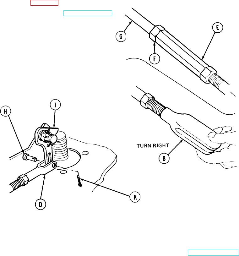
Turn clevis (B) and screw coupling (E) on
9.
rear intermediate rod (G) the recorded number
of turns (page 17-29, step 4 and NOTE).
Close rear drain valve (TM 5-5420-202-10)
10.
(B)
and install clevis pin (H) through holes in
clevis (B) and hole in lever (J).
Using pliers, install cotter pin (K) in
11.
hole in clevis pin (H).
Using 9/16 inch wrench, tighten coupling
12.
jamnut (F) against coupling (E) while holding
coupling (E) with another wrench.
NOTE
If valve does not operate properly, check linkage for obstructions
and adjust linkage, if necessary.
Operate valve to make sure rear drain valve opens and closes smoothly (TM 5-5420-202-10).
13.
14.
Install powerplant (page 5-14).
TA248564
End of Task
17-33