TM 5-5420-209-12
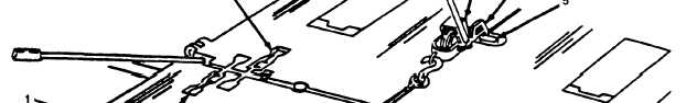
(6) When bays are together, engage bay/bay connectors (8).
Figure 2-18. Ramp Bay To Interior Bay Connection (Sheet 1 of 2).
NOTE
The top of lock drive pin screw will be 3/4 in. (1.9 cm) below roadway when lower lock drive pin is fully
engaged.
If it is difficult to engage lockpin it may be necessary to raise connector yoke on ramp bay, see Step (8).
(7) Install T wrench (9) on lower lockpin screw (10) and turn wrench clockwise to engage pin.
NOTE
Perform Step (8) only if the lower lock pin cannot be engaged.
Operate both pumps simutaneously and in unison or damage to pumps and cylinder may occur.
(8) Open pump access covers (11), set pump control lever (12) to PUMP position, open vent valve (13) and oper-
ate pumps (14) while turning T wrench (9) to engage pin.
(9) Close vent valves (13), set pump control levers (12) to TRAFFIC positions, close pump access covers (11).
(10) Repeat Steps (8) and (9) to engage remaining lower lockpin drive screw (15), (if applicable).
2-78