ARMY TM 5-5420-212-10-1
MARINE CORPS TM 08676A-10/1-1
(9)
Remove bay 12 top panel and bay 11 bottom panel (para. 4-27b. and c.).
(10) Delaunch to 7p7 (over FRB).
(11) Remove bay 11 top panel and bay 10 bottom panel.
(12) Delaunch to 6p7 (over FRB).
(13) Remove bay 10 top panel and bay 9 bottom panel.
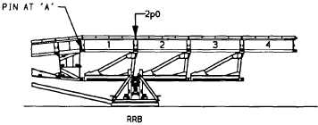
(14) Assemble and position rear roller beam (RRB). Position the RRB using longitudinal girders, then
disconnect girders from RRB and place on the ground.
(15) Position the roller beam at the height desired for delaunch. During this positioning, level both roller
beams using a carpenter’s level.
(16) Delaunch to 2p0 (over FRB).
NOTE
The center of gravity of the bridge is over the front roller beam. It is at this point that any minor
adjustments in the rear roller beam placement must be made. Ensure that the bridge will come to
rest on the roller beams correctly. The bridge should rest between the flanges of the rollers, not
on top of them.
(17) Recover landing roller pedestal.
(18) Boom bridge to 3p4 (over RRB).
(19) Remove bay 9 top panel and bay 8 bottom panel.
(20) Boom bridge to 3p0 (over RRB).
(21) Remove bay 8 top panel and bay 7 bottom panel.
(22) Boom bridge to 2p3.
(23) Remove bay 7 top panel and bay 6 bottom panel.
(24) Boom bridge to 1p7.
(25) Remove bay 6 top panel, bay 5 bottom panel, one LNH (8N1), bay 5 top panel and bay 4 bottom panel.
Do not remove bay 4 top panel.
(26) Remove remainder of launching nose.
NOTE
Additional boom to panel points 1 p7 and 2p0 are required to ease the removal of the last four
bottom panels and the pin in the last top panel and junction.
(27)
Boom bridge to 2p0 (over RRB).
6-61