ARMY TM 5-5420-212-10-1
MARINE CORPS TM 08676A-10/1-1
(2)
LINK ANCHOR SHORT. Takes the tension load from the anchor junction blocks and transfers it to the fork end
anchors and the bottom panel pins.
(3)
LINK ANCHOR LONG. Takes the tension load from the anchor junction block and transfers it to the fork end
anchors and the bottom panel pins.
(4)
ANCHOR JUNCTION BLOCK. Connects the link anchors to the long reinforcing link attached to the post
tensioning assembly. The block has a guide system built into it which allows the nose pin to be inserted easily
when connecting the reinforcing link.
(5)
CARRYING BAR BRACKETS. The anchor assembly has six brackets, four on the link anchor long and two on the
link anchor short. The two brackets on the link anchor short are used only to position the link for connection to the
pins in the bottom panel.
(6)
BRACING PINS AND HOLES. For positioning of the fork end anchors in either the transit or operational position.
The bracing pins are always inserted from the top of the fork.
CAUTION
Ensure four bracing pins stay with this component. Do not use these bracing pins in any other
component.
(7)
IDENTIFICATION PLATE. The component serial number is marked on this plate.
(2)
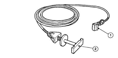
Anti-flutter Tackle
The anti-fluttertackle is used between top panels and reinforcing links to reduce vibrational flutter which may be
caused by side winds or crossing vehicles. For all link reinforced bridges, two sets of anti-fluttertackle should be fitted
under each girder approximately mid span. Connection is made by inserting the toggle bar into the elongated slot of the
link. The block is pushed against the spring and rotated 900 which locks it into position. The hook end is then placed over
the carrying bar bracket of the top panel.
(1)
HOOK. Connects to the carrying bar bracket of a top panel.
(2)
TOGGLE BAR. Connects the lower end of the tackle to the link. It is spring loaded to keep it in the locked
position.
ANTI-FLUTTER
TACKLE
1-49