
TM 5-5420-226-20-2
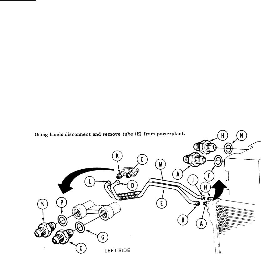
LEFT OUTER AND INNER ENGINE-TO-TRANSMISSION OIL LINE TUBE ASSEMBLIES
REPLACEMENT (Sheet 2 of 4)
NOTE
Place rags under fittings (H & A and K & C). Upon removing tubes and
fittings, seal powerplant openings with plastic barrier material and
masking tape to prevent u necessary exposure to moisture and con-
tamination. Remove plastic barrier material and masking tape when
installing tubes and fittings.
REMOVAL:
1.
Using 1-5/8 inch wrench to hold adapter (A), use 1-1/2 inch wrench and loosen connector
(B).
Using 1-5/8 inch wrench to hold adapter (C), use 1-1/2 inch wrench and loosen connector (D).
2.
3.
Using 1-5/8 inch wrench, remove adapters (A and C) and gaskets (F and G). Throw gaskets
4.
away.
Using 1-5/8 inch wrench to hold adapter (H), use 1-1/2 inch wrench and loosen connector (J).
5.
Using 1-5/8 inch wrench to hold adapter (K), use 1-1/2 inch wrench and loosen connector (L).
6.
Using hands disconnect and remove tube (M) from powerplant.
7.
Using 1-5/8 inch wrench, remove adapters (H and K) and gaskets (N and P). Throw gaskets
8.
away.
TA107538
Go on to Sheet 3
6-69