
TM 5-5420-228-20-2
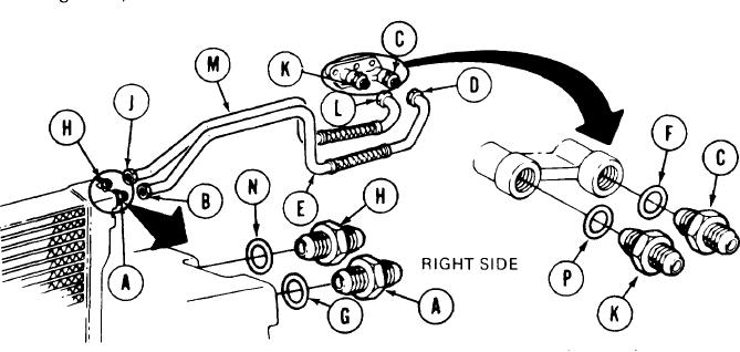
RIGHT OUTER AND INNER ENGINE TO TRANSMISSION OIL LINE TUBE ASSEMBLIES
REPLACEMENT (Sheet 2 of 4)
NOTE
Place rags or drip pan under transmission and oil cooler
Before removing tubes and fittings, seal
adapters.
powerplant openings with plastic barrier material and
masking tape to prevent unnecessary exposure to moisture
and contamination. Remove plastic barrier material and
masking tape when installing tubes and fittings.
REMOVAL:
1.
Using 1-5/8 inch wrench to hold adapter (A), use 1-1/2 inch wrench and loosen connector
(B).
2.
Using 1-5/8 inch wrench to hold adapter (C), use 1-1/2 inch wrench and loosen connector
(D).
3.
Using hands, disconnect and remove tube (E) from powerplant.
Using 1-5/8 inch wrench, remove adapters (A and C) and gaskets (F and G). Throw gaskets
4.
away.
Using 1-5/8 inch wrench to hold adapter (H), use 1-1/2 inch wrench and loosen connector
5.
(J).
Using 1-5/8 inch wrench to hold adapter (K), use 1-1/2 inch wrench and loosen connector
6.
(L).
Using hands disconnect and remove tube (M) from powerplant.
7.
Using 1-5/8 inch wrench, remove adapters (H and K) and gaskets (N and P). Throw gaskets
8.
away.
TA248057
Go on to Sheet 3
6-65