
TM 5-5420-226-20-3
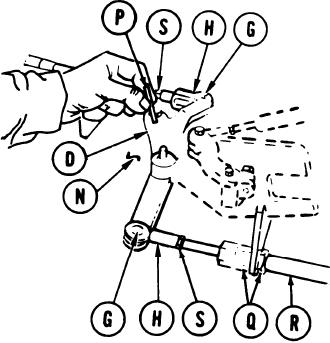
PARKING BRAKE PAWL AND BELL CRANK ADJUSTMENT (Sheet 4 of 4)
10.
Rotate bellcrank assembly (D) to aline holes in bellcrank (D) and bracket (N). Insert 1/8
inch locating pin (P) through holes in bellcrank (D) and bracket (N).
NOTE
Locating pin (P) must slide up and
down freely in alinement holes
when clevis pins (G) are installed.
NOTE
It may be necessary to remove
locating pin (P) and move bel~lcrank
assembly (D) before clevis (H) can be
adjusted.
11.
Using two 15/16 inch wrenches, loosen two
nuts (Q) and move cable assembly (R) until
clevis pin (G) and locating pin (P) slide
freely in their respective holes. If clevis pin
(G) will not slide in freely, loosen jamnut (S)
and adjust clevis (H) until clevis pin (G) will
slide in freely.
12.
Install clevis pin (G) and, using slip joint
pliers, install washer and new cotter pin on
clevis pin (G).
13.
Using two 15/16 inch wrenches, tighten nuts
(Q).
14.
If loosened, use 9/16 inch wrench to tighten
nut (S).
15.
Remove 1-1/8 inch gage block and locating
pin.
16.
Repeat steps 1 thru 16 for the opposite side
brake.
17.
Using pry bar, rotate bellcrank (D)
clockwise to release brakes.
18.
Using socket, install brake housing cover
and new cover gasket.
19.
Install powerplant (page 5-14).
End of Task
TA169257
13-133 / ( 13-134 blank)