
TM 5-5420-227-24
OVERHEAD CYLINDER RELIEF VALVE (RV9) AND FLOW REGULATOR (PCV1)
REPLACEMENT (Sheet 3 of 4)
INSTALLATION:
NOTE
Remove all caps and plugs as necessary during installation.
Before installation, use pipe tape on all male threads. Start
tape on second thread so tape will not enter hydraulic
system.
1.
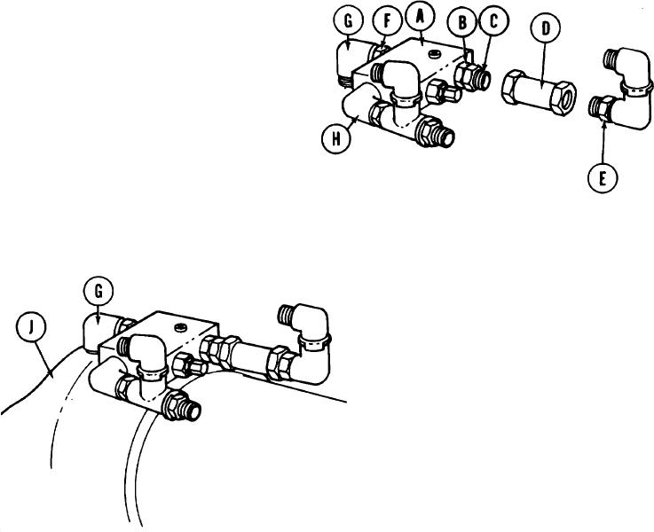
Using care to prevent damage, clamp relief valve (A) in vise.
NOTE
Locate and aline parts as shown in illustrations to make
sure connecting parts mate at final assembly.
2.
Using 1-1/8 inch wrench, install nipple (B) and attached bushing (C) in hole next to pressure
adjustment fitting.
Holding bushing (C) with 1-3/8 inch wrench,
3.
use 15 inch adjustable wrench to install
regulator (D) on bushing (C).
4.
Using 1-3/8 inch wrench, install bushing
(E) and attached parts.
5.
Using 1-1/8 inch wrench, install nipple
(F) and attached elbow (G).
Using 12 inch adjustable wrench, install
6.
elbow (H) and attached parts.
7.
Remove relief valve (A) and attached parts from vise.
Using adjust able wrench, install
8.
elbow (G) and attached parts in
cap end of cylinder (J).
TA170332
Go on to Sheet 4
3-106