
TM 5-5420-227-24
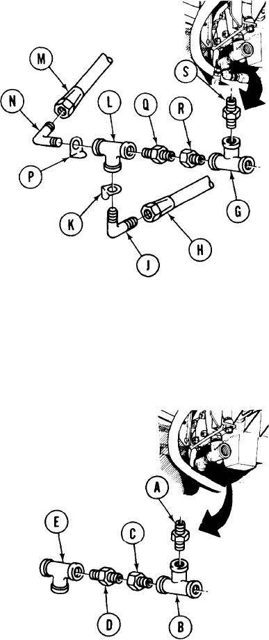
VALVE BANK RETURN PORT FITTINGS REPLACEMENT (Sheet 2 of 3)
6.
Using 1-1/4 inch wrench, remove hose
assembly "CR" (H) from elbow (J).
Using 12 inch adjustable wrench, remove
7.
elbow (J) and collar (K) from tee (L).
8.
Using 1-1/4 inch wrench, remove hose
assembly "F" (M).
Using adjustable wrench, remove elbow (N)
9.
and collar (P).
10.
Using 1-1/8 inch wrench on nipple (Q), use
12 inch adjustable wrench to remove tee (L).
11.
Using 1-3/8 inch wrench on bushing (R), use
1-1/8 inch wrench to remove nipple (Q).
12.
Using 1-3/8 inch wrench, remove bushing (R)
from tee (G).
While holding nipple (S) with 1-3/8 inch wrench, use 12 inch adjustable wrench to remove
13.
tee (G) from nipple (S).
Using 1-3/8 inch wrench, remove nipple (S) from valve bank.
14.
INSTALLATION:
NOTE
Before installation, use pipe tape on all male threads. Start tape on second thread
so tape will not enter hydraulic system.
1.
Using 1-3/8 inch wrench, install nipple (A)
into valve bank.
2.
Using 1-3/8 inch wrench to hold nipple (A),
use 12 inch adjustable wrench to install tee
(B).
3.
Using 1-3/8 inch wrench, install bushing (C).
4.
Using 1-3/8 inch wrench to hold bushing (C),
use 1-1/8 inch wrench to install nipple (D).
5.
Holding nipple (D) with 1-1/8 inch wrench,
use 12 inch adjustable wrench to install tee
(E).
TA170406
Go on to Sheet 3
3-181