
TM 5-5420-227-24
HYDRAULIC PUMP REPAIR (Sheet 3 of 11)
NOTE
Do not allow parts to separate while placing
pump upright,
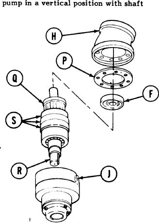
With help of second technician, carefully place
9.
end down.
While manually pushing down evenly on valve
10.
plate (F), ease subdeck housing (H) off bear-
ing housing (J).
NOTE
Note position of valve pIate (F) for assembly.
11.
Manually remove valve plate (F) and gasket (P).
Throw gasket (P) away.
CAUTION
Do not pull up on cylinder block (Q), as it will separate
from drive shaft (R) and damage piston surfaces.
12.
While manually pressing down on bearing
housing (J), pull up on three bearings (S)
to remove drive shaft (R) with cylinder
block (Q) attached.
13.
While holding three bearings (S), place other hand over cylinder block (Q) and turn drive
shaft (R) and assembled parts up.
Go on to Sheet 4
TA170521
4-44