
TM 5-5420-227-24
VALVE BANK ASSEMBLY AND BRACKETS REPLACEMENT (Sheet 13 of 17)
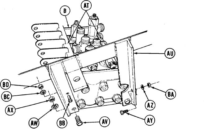
Manually position identification
36.
plates (AT) on valve bank (B).
Manually position two brackets (AU)
37.
on valve bank (B) (one on each end).
Manually install four screws (AV), new
38.
lockwashers (AW), and nuts (AX).
Using 3/4 inch wrench to hold nuts
39.
(AX), use 3/4 inch socket to tighten
screws (AV).
Manually install two screws (AY), new lockwashers (AZ), and nuts (BA).
40.
Using 1/2 inch wrench to hold screw (AY), use 1/2 inch socket to tighten nut (BA),
41.
Manually install two screws (BB), new lockwashers (BC), and nuts (BD).
42.
Using 7/16 inch wrench to hold screws (BB), use 7/16 inch socket to tighten nuts (BD).
43.
Using second technician, position valve bank assembly (B) and brackets (AU) in vehicle.
44.
Go on to Sheet 14
TA170541
4-65