
TM 5-5420-228-24
H Y DRAU LI C FLU I D FI LT ER ASSEM BLY REPAI R (She e t 8 of 8 )
21.
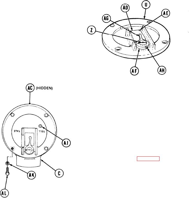
Manually place indicator plate (AD)
in position on cover (U).
22.
Using hammer, install four new drive
screws (AE).
23.
Manually place washer (AF) and indicator
lever (AG) on shaft (Z) over "FILTER CLEAN"
on indicator plate (AD).
Using 9/64 inch screw key, install setscrew
24.
(AH).
H I DDEN
25.
Using 1/4 inch screw key, install pipe
plug (AJ).
26.
Position filter assembly (AC) in housing
(C) and aline holes.
27.
Manually install four lockwashers (AK)
and screws (AL).
28.
Using 1/2 inch socket, tighten four screws
(AL).
29.
Install filter assembly (page 3-209).
End of Task
T A2 5 1 6 1 3
3-218