TM 5-5420-228-24
H Y DRAU LI C FLU I D FI LT ER ASSEM BLY Re pla c e m e nt (She e t 2 of 3 )
10.
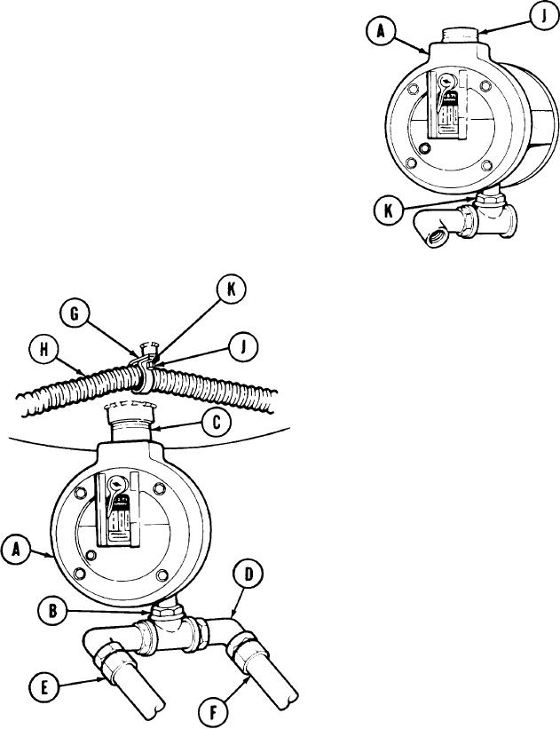
Using adjustable wrench, remove reducer
(K) and attached parts from filter assembly
(A).
11.
Use pipe wrench to remove nipple (J).
INSTALLATION:
N OT E
Be fore inst a lling, use pipe t a pe on a ll
St a rt t a pe on se c ond
m a le t hre a ds.
t hre a d so t a pe doe s not e nt e r hydra u-
lic system.
1.
Place filter assembly (A) in vise.
Using adjustable wrench, install reducer (B)
2.
and attached parts.
Use pipe wrench to install nipple (C) in
3.
filter assembly (A).
Using pipe wrench, install nipple (C) with
4.
attached filter assembly (A) in vehicle.
Using adjustable wrench, install and aline
5.
elbow (D).
Using 1-1/2 inch wrench, install hose
6.
assembly "CY" (E).
Using adjustable wrench, install collar and
7.
hose assembly "CZ" (F).
Place clamp (G) with hose (H) in position.
8.
Using 7/16 inch wrench, install screw (J)
9.
and lockwasher (K).
Service hydraulic reservoir [L() 5-5420-202-12).
10.
T A2 5 1 6 0 4
Go on to Sheet 3

