TM 5-5420-278-10
0009 00
0009 00-7
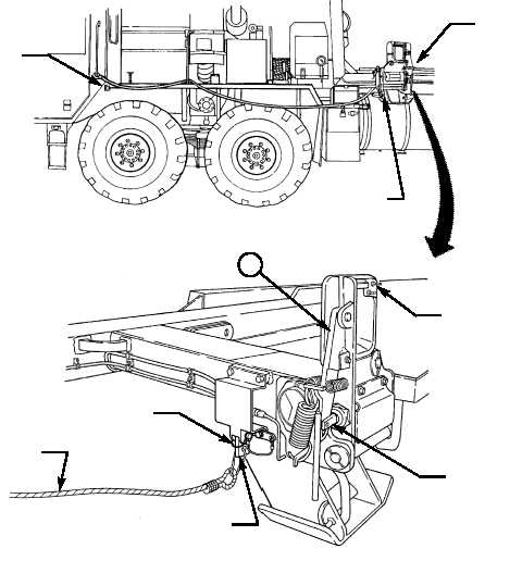
BRIDGE ADAPTER PALLET CONTROLS AND INDICATORS (Contd)
FRONT PIN LOCK RELEASE MECHANISM — The jaw and latch on the
front pin lock assembly that is released manually by pulling a lever or
pneumatically by activating a control valve. To manually open the jaw on
either front pin lock, pull the lever on the latch toward the vehicle cab. During
a free launch of the bay, both front pin locks are released at the same time by
a pneumatic cylinder on each lock assembly. The pneumatic cylinders are
activated simultaneously by a single control valve located on the BAP, at the
driver's side. To operate the control valve, connect a lanyard to the control
valve lever, remove the safety pin from the same lever, and pull the lanyard
toward the vehicle cab.
G
FRONT PIN
LOCK
ASSEMBLY
LANYARD
G
JAW
LEVER AND
CYLINDER
SAFETY
PIN
LANYARD
CONTROL
VALVE
LEVER

