TM-5-5420-279-10
1.1.4.4
The palletized loads are then positioned at both sides of the launch vehicle in readiness
for bridge building.
1.1.4.5
The vehicle must be leveled by the A-frame and crane stabilizers and pinned in position
before the crane operator retrieves a section of launch beam. The beam section is then
connected to the forward launch beam section by inserting pins through the jaws at the
top and then bottom of launch beam sections. A guide system on the launch beam aids in
the alignment of the jaws to facilitate pin insertion.
1.1.4.6
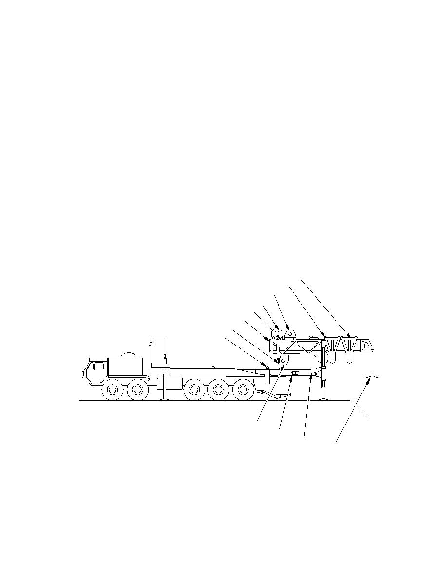
As the launch beam is boomed out across the gap, the crane operator retrieves and
places in position the next section of the launch beam. The sequence continues until the
launch beam assembly is complete, with eight sections being required for the full span.
The launch frame articulator cylinders then lower the launch beam far end until the far
bank support contacts the ground to support the assembled beam. The far bank support
is self-leveling and does not require any manual intervention.
1.1.4.7
During bridge deployment, the location of the palletized loads, and thus the modular
bridge sections, is critical to the speed of the operation. This sequence is given in detail
later in this manual.
1.1.4.8
The articulator cylinders are detached from the slide frame cross member and stowed
under the launch frame by the articulator stow cylinders. The upper A-frame beam is then
raised and pinned in the bridge deployment position, and the A-frame support struts are
lowered. This provides clearance for the modular bridge sections to be launched through
the A-frame.
FAR BANK CARRIAGE
HOME BANK CARRIAGE
UPPER WINCH
LAUNCH BEAM DRIVE
LAUNCHING FRAME
FORWARD LAUNCHING BEAM
LAUNCHING FRAME ARTICULATOR
TILT ROLLERS
LOWER WINCH
SLIDE FRAME ASSEMBLY
`A' FRAME ROTATE CYLINDER
FAR BANK SUPPORT
WF/0002
Figure 1.2 Launcher Vehicle Extended
1-5


