TM-5-5420-279-10
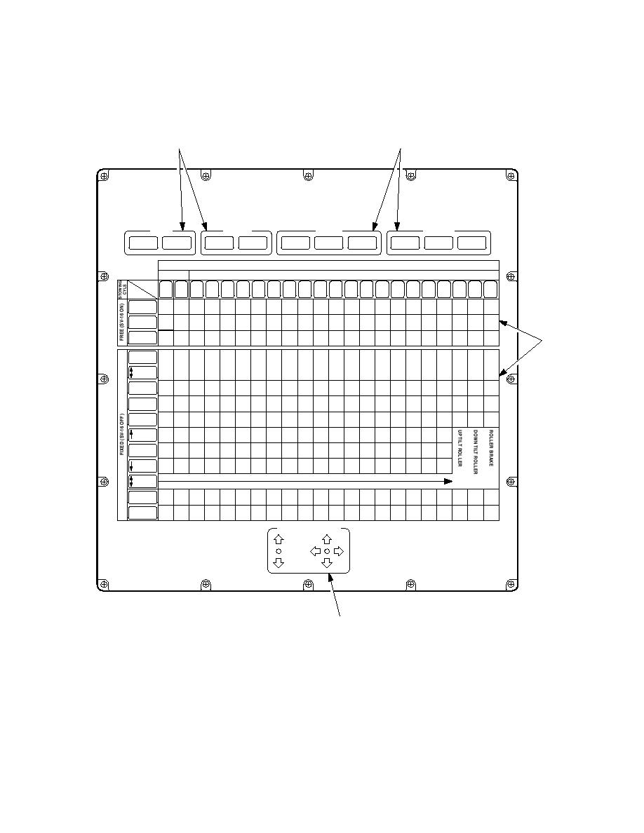
Launch Frame Electrical Control Enclosure
2.4.6.1
The launch frame electrical control enclosure is mounted on the left side of the launch
frame and interfaces between the chest pack and the launcher hydraulic solenoids.
3
3
BRIDGE DEPLOYMENT SOLENOID MIMIC
PANEL
INTERFACE ENCLOSURE
SUPPLIES
LAUNCH CONTROLLER
CHEST PACK
SIGNALS
STATUS
SIGNALS
SIGNALS
LAUNCH
BRIDGE
ROLLER BRAKE
CONTROLLER
ROLLER
CHEST PACK
MAJOR
MINOR
FAULT
CONTROLLER
ENABLE
DEPLOYMENT
TOGGLE SW
HEALTHY
BRAKE
CONNECTED
FAULT
FAULT
SOLENOID VALVES
PV
SV
SOLENOID
21
13a
13b
1
15a
15b
16
17a
17b
18a
18b a, b, c
1b
2
3
4
5
6
7
8
9
10
1a
BUILD
14a
14b
d
FUNCTION
UP
UP
BEAM
UP DOWN
DOWN
DOWN
ANGLE
IN
IN
IN
IN
BEAM
ON
ON
ON
OUT
IN
IN
OUT
OUT
OUT
OUT
OUT
DRIVE
UP
FAR BANK
DOWN DOWN
UP DOWN ON
1
DOWN
SEAT
STOW
ARTIC
STOW
EXT
RET
A FRAME
DOWN UP
ON
RAISE
MODE
SELECT
IN
IN
IN
IN
IN
IN
IN
CARRIAGE
OUT
IN
OUT
OUT
OUT
OUT
OUT
OUT
OUT
EMPTY
IN
IN
IN
IN
IN
HIGH
IN
OUT
OUT
IN
OUT
OUT
OUT
OUT
OUT
BANK
IN
IN
IN
IN
LEVEL
IN
OUT
OUT
IN
OUT
OUT
OUT
OUT
BANK
IN
IN
IN
IN
IN
LOW
OUT
IN
OUT
IN
OUT
OUT
OUT
OUT
OUT
BANK
TILT
AVAILABLE
ROLLER
UP
UP
UP
UP
BRIDGE
UP DOWN
DOWN
DOWN DOWN
DOWN
LIFT
IN
IN
IN
IN
TOP
OUT
IN
OUT
OUT
OUT
OUT
WINCH
CHEST PACK
JOYSTICK ANNUNCIATORS
2
686A351b
Figure 2. 25 Launch Frame Electrical Control Enclosure
2.4.6.2
With the enclosure door open the action/solenoid matrix (1) the chest pack joystick
annunciation panel (2) and status caption lights (3) are visible. The matrix enables
fault finding to be carried out. The chest pack joystick annunciation panel shows the
position of both the chest pack joysticks. This enables confirmation of movement of a
joystick and that the signal from the chest pack has arrived at the launch frame
electrical control enclosure.


