TM-5-5420-279-10
3.4.3.14
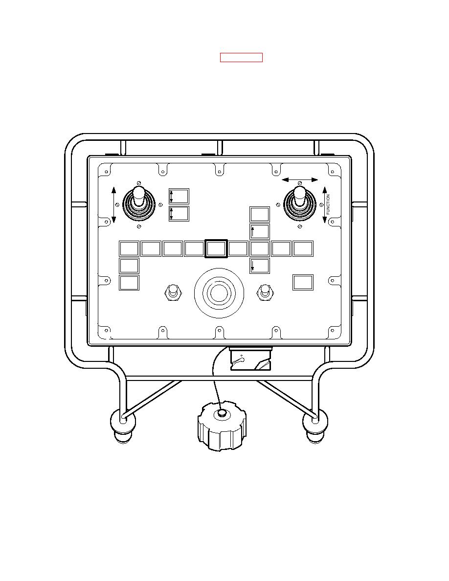
function is active. For this function to operate correctly the A-frame pins need to be
removed. Movement of the joystick forward causes the A-frame raise cylinders to extend
raising the A-frame to the upper position. The A-frame should be raised to a point where
the A-frame pins can be re-inserted and then the A-frame is lowered onto the pins. With
the pins removed, movement of the joystick rearward causes the A-frame raise cylinders
to retract and lower the A-frame. The A-frame should be lowered until it sits on the lower
captive pins at which point the A-frame pins can be reinserted.
FUNCTION
SELECT
TILT
ROLLER
CARRIAGE
STOW
EMPTY
HIGH
BANK
BEAM
A FRAME
FARBANK
MODE
BEAM
STOW
=LEVEK
L
TOP
BRIDGE
DRIVE
RAISE
SEAT
SELECT
ANGLE
ARTIC
BAN
WINCH
LIFT
LOW
EMERGENCY STOP
POWER
BANK
ROLLER
BRIGHT
OFF
FAULT
BRAKE
OFF
ON
DIM
OFF
ROLLER BRAKE
PUSH TO STOP - TWIST TO RESET
686A356e
NOTE
In this mode, forward or rearward movement of the joystick on the chest pack results in no
physical effect on the hydraulic system.
3-30


