TM-5-5420-279-10
NOTE
If the locking pins are difficult to disengage, press and hold momentarily the DEPLOY
pushbutton on the A-frame fold panel of the interface cabinet.
3.6.3.8
Make sure personnel are clear from the area around the A-frame.
3.6.3.9
On the A-frame fold panel of the interface cabinet, press and hold the PARK pushbutton.
Make sure the hydraulic cylinders retract and fold the outer A-frame legs to the stowed
position.
3.6.3.10
Release the PARK pushbutton when the outer A-frame legs are in the folded position. On
the A-frame fold panel of the interface cabinet, make sure the DEPLOYED caption goes
off.
3.6.3.11
Install the locking pins and their R clips at the hinge point of the upper transverse beam to
lock the outer A-frame legs in the folded position.
NOTE
The long pin is inserted from the REAR to the FRONT in the top hole and the short pin is
inserted from the FRONT to the REAR in the bottom hole.
3.6.3.12
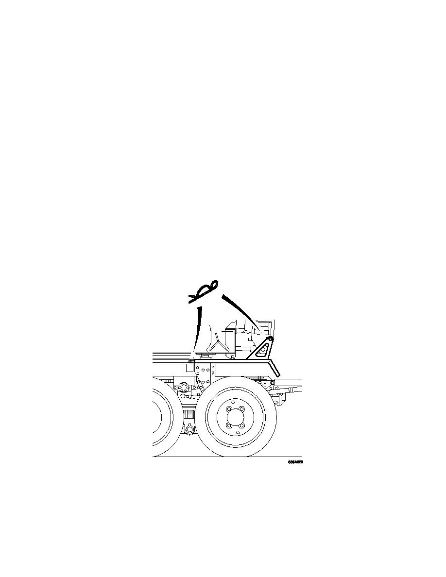
Refit the mudguards to the launch vehicle ensuring shootbolts and front peg are fully
engaged and R clipped.
Position of Mudguard R clips
3-55


