TM-5-5420-279-10
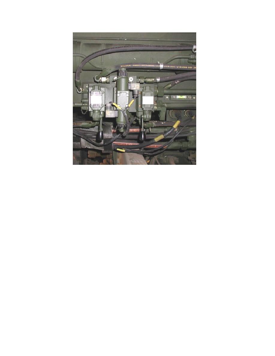
Figure 3. 25 A-Frame Stabilizer Controls
Stowing the A-Frame
Disengage the shootbolts securing the A-frame in the vertical position.
3.6.3.2
Disconnect the chest pack and umbilical cable from the connection point on the A-frame
stabilizer leg; replace all electrical connector dust covers.
3.6.3.3
Stow the chest pack and umbilical cable in the toolbox located above the front wheels on
the left hand side of the vehicle.
NOTE
If the shootbolts are difficult to disengage, press and hold momentarily the DEPLOY
pushbutton on the A-frame rotate panel of the interface cabinet.
3.6.3.4
Make sure personnel are clear from the area around the A-frame.
3.6.3.5
On the A-frame rotate panel of the interface cabinet, press and hold the PARK
pushbutton. Make sure the hydraulic cylinders extend and rotate the A-frame to the
stowed position. Ensure that the A-frame is sitting on the rubber supporting pads.
3.6.3.6
Release the PARK pushbutton when the A-frame is fully rotated to the stowed position.
Make sure the LAUNCHER DOWN caption illuminates.
3.6.3.7
Remove the R clips and the locking pins in the A-frame upper and lower transverse
beams which lock the outer A-frame legs in the spread position.


