TM-5-5420-279-10
68. Add home bank ramp and pin.
See step 47 above.
69. Reposition slings on ramp to allow for end beam.
70. Add ramp module to bridge.
Module will not connect.
Dowels will not connect.
Ensure that all shootbolts on both modules are fully lowered. Connect
Dowels and shootbolt.
WARNING
CRUSH HAZARD. DO NOT INSERT FINGERS IN PIN HOLES, WHEN CLEANING
OUT ACCUMULATED DIRT USE A SUITABLE TOOL. SEVERE INJURY CAN
RESULT IF THIS INSTRUCTION IS NOT ADHERED TO.
Clean any dirt from pin holes.
Pins.
Ensure that all the weight of the ramp module is released from the crane.
Ensure that the crane and the A-frame are level.
Pull down on the open end of the module (rear of the bridge).
Replace ramp module.
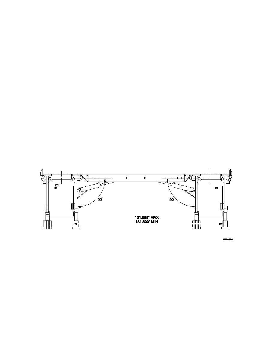
♦ Check the width between the ramp module inner jaw outer face and the
outer jaw inner face. The measurement between the faces of the jaws
should be between; 131.685in (3344.799mm) MAX and 131.6in
(3342.64mm) MIN.
♦
If measurement is under size the module is not fully open, carry out ramp
module does not open procedure detailed in step 47. If measurement is
over size, check the tightness of the damper to side skin connection.
Tighten damper to side skin connection and re-check measurement.
Report over size measurement to maintenance.
♦ Retrieve last parallel module and replace.
71. Remove and stow end beam guides, adapters, removable rollers and tilt
rollers.
Removable rollers.
Ensure that the removable roller aligns with the white marks on the slide
frame. Tap side ways until free.
End beam guides.
Check the operation of the catch and for any deformation of end beam guide
spigots. Report any damage/deformation to maintenance.
9-44


