
TM 5-5420-280-23&P
0004 00
INTRODUCTION TO TROUBLESHOOTING (Contd)
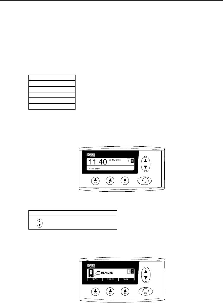
(4) OPERATIONAL POSITION
In the operational position, date and time are shown. This is the mode that is shown during
normal operation.
(5) MENU SYSTEM
(a) When you read about the different menus, it is recommended also to look at the menu
overview.
(b) The system consists of five menus and their submenus.
Menus
Mode
Information
Settings
Measure
Properties
NOTE
Function button [F3] is used to change SCOPE channel to a graph
display.
(c) On the display there are three function buttons [F1], [F2], or [F3]. These are used to select
different functions in the system's submenus. Above every function button, there is an
informative tab for the current function.
(6) UP/DN BUTTON
(a) In the submenus, the UP/DN button is used to browse the list.
Indication
Description
Browse in list
(b) The indication is shown in the upper right corner of the character window.
(7) MEASURE
This menu contains functions for measuring on the different channels.
0004 00-3