TM 5-5420-280-23&P
0004 00
INTRODUCTION TO TROUBLESHOOTING (Contd)
(11) Press ACTION buttons 1 or 2 (TM 5-5420-280-10) and check if light is on control valve solenoids
KY1 and KY8 or KY10 are lit. If lights operate when ACTION buttons are depressed, system is
operating.
(12) If necessary, repeat steps through launch and retrieval to check all control valve solenoid lights.
(13) If RCU SPS is checked first, then all that can be assumed is that a fault is the wiring between
the lights or solenoids and the SPS.
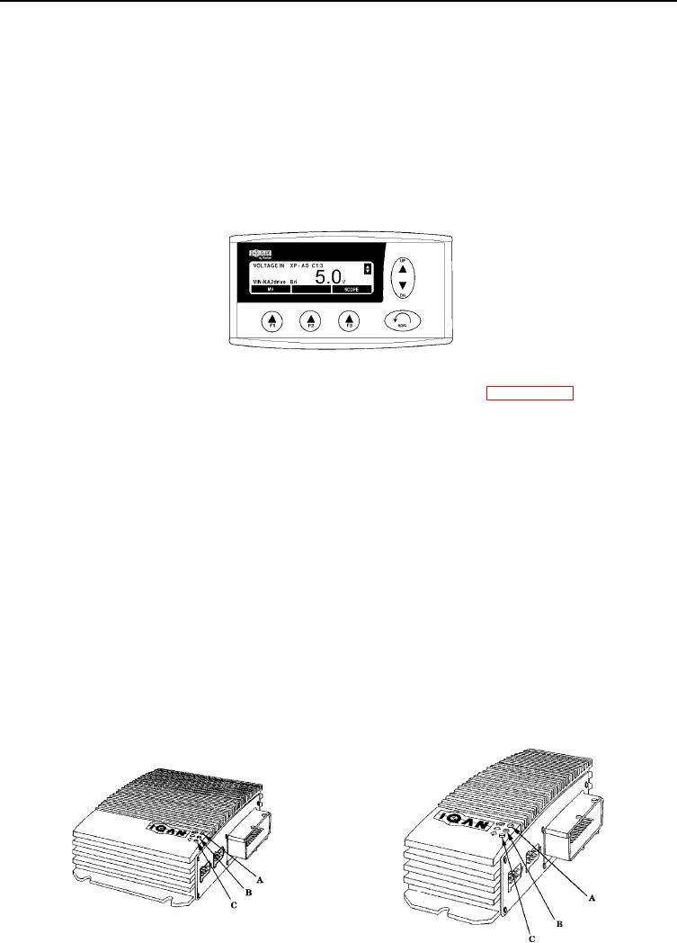
(14) If checking voltage in VIN-KA2 drive, scope will shown 5.0 V. This is 24 volts the system must
have 5.0 V to operate.
h. Check Operation of IQAN-XP and IQAN-XS
(1) Loosen four screws and open cover on electrical control box. Refer to WP 0049 00.
(2) Turn on RCU (TM 5-5420-280-10).
(3) The expansion power XP module and the expansion signal XS module have three LED lights
that indicate power supply to module A, heart B, and arrow C.
(4) Explanation of LED lights and flashes.
a. Indication for supply voltage. LED A with a firm green light indicates supply voltage. If the
LED is out, the supply voltage is missing.
b. Status indication for IQAN-XP and IQAN-XS. Status=correct, indicated by LED for heart B
and arrow C flashes alternately with a green light. Status=some errors have been detected,
indicated by LED for heart B is out and LED for arrow C flashes with a green light.
Explanation of flashes:
One flash arrow C indicates fault on inputs/outputs or that the supply voltage is too low
or high.
Two flashes arrow C in a row indicates that internal temperature in the unit is too low
or high.
Three flashes arrow C in a row indicates that the fault is related to the CAN-bus.
Four flashes arrow C in a row indicates an internal fault on the hardware in the unit.
0004 00-7

