
TM 5-5420-280-23&P
0078 00
FRONT EXPANDING CYLINDERS HYDRAULIC FLOW DIVIDER, MAIN EXPANDING CYLINDERS
HYDRAULIC FLOW DIVIDER, REAR EXPANDING CYLINDERS HYDRAULIC FLOW DIVIDER,
FORWARD SUPPORT WHEEL CYLINDERS FLOW DIVIDER, AND REAR SUPPORT WHEEL CYLINDERS
FLOW DIVIDER REPLACEMENT (Contd)
REMOVAL
i.
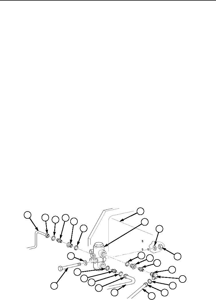
Rear Support Wheel Cylinders Flow Divider
1. Loosen nut (2) and remove steel tube (1) and tube seal (3) from adapter (4) on reducer (5) on flow
divider (8). Discard tube seals (3).
2. Loosen nut (15) and remove steel tube (16) and tube seal (3) from elbow (14) on adapter (12) on flow
divider (8). Discard tube seals (3).
3. Loosen nut (18) and remove steel tube (17) and tube seal (19) from adapter (20) on flow divider (8).
Discard tube seals (19).
4. Loosen nut (13) and remove elbow (14) and adapters (12) and (4) from reducers (5) and (11).
5. Remove three locknuts (10), washers (9), screws (21) washers (22), and flow divider (8) from
crossmember (7). Discard locknuts (10).
6. Remove adapter (20), reducers (5) and (11), and three O-rings (6) from flow divider (8). Discard O-
rings (6).
INSTALLATION
NOTE
Apply a light coat of hydraulic oil to O-rings at installation.
The pallet hydraulic system is self-bleeding, and with exception of
the telescopic tube hydraulic cylinders, there is not requirement for
bleeding air from the system.
j. Rear Support Wheel Cylinders Flow Divider
1. Install three new O-rings (6), adapter (20), and reducers (5) and (11) on flow divider (8).
2. Install flow divider (8) on crossmember (7) with three washers (22), screws (21), washers (14), and
new locknuts (10).
3. Install adapters (12), and elbow (14) on reducer (11) and tighten nut (13) on elbow (14).
4. Install adapters (4) on reducer (5), and adapter (20) on flow divider (8).
5. Install new tube seal (19) and steel tube (17) on adapter (20) on flow divider (8) and tighten nut
(18).
6. Install new tube seal (3) and steel tube (16) on elbow (14) on flow divider (8) and tighten nut (15).
7. Install new tube seal (3) and steel tube (1) on adapter (4) on flow divider (8) and tighten nut (2).
7
1
2
4
3
5
8
6
9
6
22
10
11
12
13
6
20
14
19
3
21
18
17
15
16
END OF WORK PACKAGE
0078 00-8