
TM 5-5420-280-23&P
0079 00
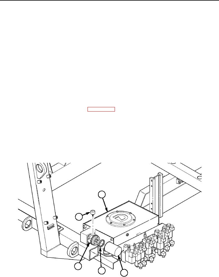
HYDRAULIC SYSTEM FILTER ASSEMBLY AND GAUGE REPLACEMENT (Contd)
REMOVAL
NOTE
Have container ready to catch oil.
1.
Remove oil filter (2) and O-ring (3) from oil filter housing (4) on hydraulic reservoir (1). Discard oil
filter (2) and O-ring (3).
2.
Remove gauge (5) from oil filter housing (4).
INSTALLATION
NOTE
Apply a light coat of hydraulic oil to O-ring at installation.
1.
Apply sealing compound to thread of gauge (5) and install gauge (5) on oil filter housing (4).
2.
Install new O-ring (3) and new oil filter (2) on oil filter housing (4).
3.
Fill hydraulic reservoir (1) at auxiliary hydrualic reservoir until oil level in main hydraulic reservoir
(1) is at center of site glass. Refer to WP 0016 00.
NOTE
The pallet hydraulic system is self-bleeding, and with exception of
the telescopic tube hydraulic cyclinders, there is no requirement for
bleeding air from the system.
4.
Operate hydraulic system and check for leaks. Refer to TM 5-5420-280-10.
1
5
4
3
2
END OF WORK PACKAGE
0079 00-2