
TM 5-5420-280-23&P
0091 00
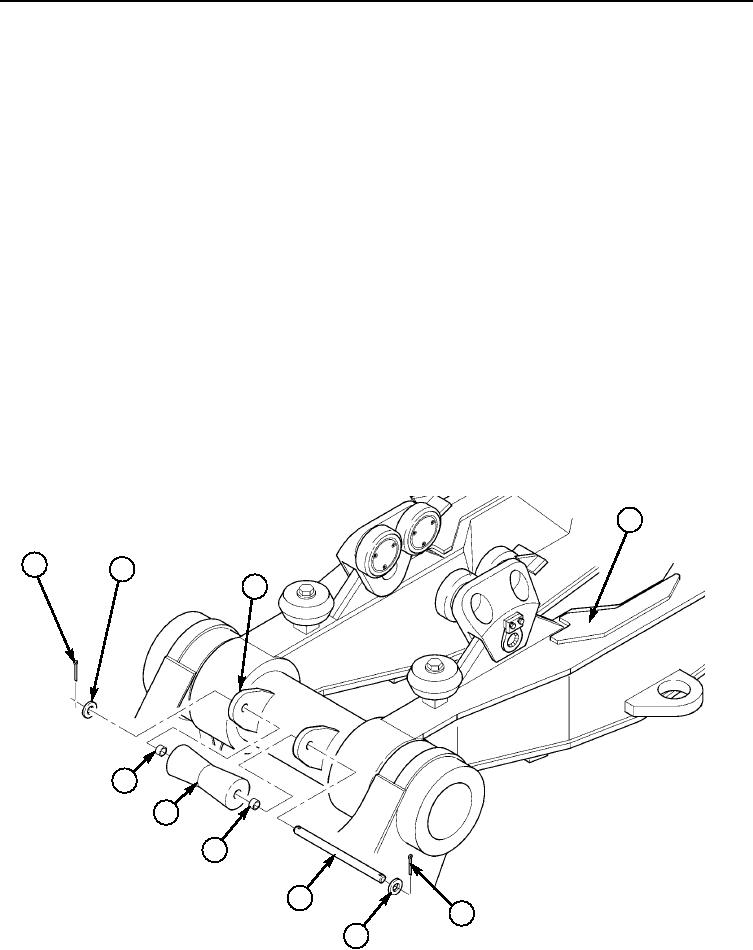
LAUNCH BOOM ROPE GUIDE ROLLER REPLACEMENT (Contd)
REMOVAL
1.
Start Launch Power Unit (LPU) or CBT, remove retaining pin from launch boom (4) and depress
KY1 and KY18 control valves simultaneously to lower launch boom (4) to -90-degrees position.
Release control valves and shut down LPU.
2.
Remove two cotter pins (1), washers (2), pin (5), and rope guide roller (7) from two launch boom
brackets (3) on launch boom (4). Discard cotter pins (1).
3.
If damaged or worn, remove two bushings (6) from rope guide roller (7).
INSTALLATION
NOTE
Apply a light coat of grease to bushings and pin at installation.
1.
If removed, install two bushings (6) on rope guide roller (7).
2.
Install rope guide roller (7) between launch boom brackets (3) on launch boom (4) with pin (5), two
washers (2), and new cotter pins (1).
3.
Start LPU or CBT and depress KY1 and KY19 control valves simultaneously to raise launch
boom (4) to +90-degrees position. Install retaining pin on launch boom (4).
4
1
2
3
6
7
6
5
1
2
END OF WORK PACKAGE
0091 00-2