
TM 5-5420-280-23&P
0093 00
POTENTIOMETER MAINTENANCE (Contd)
REMOVAL
1.
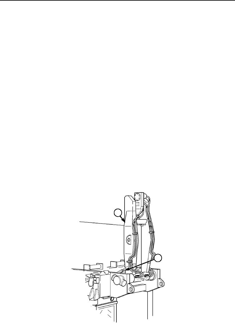
Position launch boom (1) in +90-degree position with retaining pins (2) installed.
2.
Turn on main power switch. Refer to TM 5-5420-280-10.
3.
Open Remote Control Unit (RCU) stowage box and turn on RCU by releasing STOP button. Refer to
TM 5-5420-280-10. Display screen will read TURN ON RCU. If not, perform step 4.
4.
Depress LAUNCH, ACTION 1, and ACTION 2 buttons simultaneously to return to TURN ON RCU.
5.
Depress F1 button (6).
6.
Depress ESC button (5).
7.
Depress UP/DN button (4) until display screen (3) reads MEASURE.
8.
Depress F1 button (6) until display screen (3) reads VOLTAGE IN.
9.
Depress F1 button (6).
10.
Depress UP/DN button (4) until display screen (3) reads VIN Poti (above SCALED bar (17) at
bottom left of display screen (3).
11.
Record in mV voltage value displayed above SCOPE bar (7) bottom right of display screen (3).
12.
Remove four screws (14) and potentiometer cover (13) from potentiometer adapter plate (8).
NOTE
Note position of potentiometer and wires for installation.
13.
Scribe location of potentiometer (9) on potentiometer adapter plate (8).
NOTE
Tag wires for installation.
14.
Remove two screws (11), washer (16), ground wire (10), and potentiometer (9) from potentiometer
adapter plate (8).
15.
Disconnect three wires (12) and remove and discard O-ring (15) if replacing potentiometer (9).
1
2
0093 00-2