
TM 5-5420-226-20-3
ROADWHEEL ARM REPLACEMENT (Sheet 6 of 6)
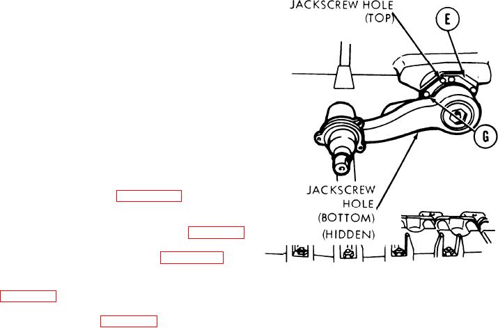
7. Position retainer (E) so that its jack-
screw holes are at top and bottom of
upper spindle.
8. Using punch, aline six mounting holes in
retainer (E) to holes in housing.
9. Put six lockwashers and screws (G) into
mounting holes.
10. Using crow foot wrench and torque wrench,
tighten six screws (G) alternately and
evenly to 95-125 lb-ft (129-169 Nm).
11. Connect adjusting link at No. 1 roadwheel
position, if necessary (page 14-78).
12. Install shock absorbers if roadwheel arm was
removed from positions No. 1, 2 and 6 (page 14-92).
13. Install suspension torsion bar (page 14-29).
14. Install hub and seal assembly, if removed
15. Install roadwheels (page 14-5).
TA169282
14-18

