
TM 5-5420-228-24
Section III. PRINCIPLES OF OPERATION
Hydraulic pressure is used to actuate various components to launch and retrieve a bridge. A
hydraulic pump is driven by the vehicle engine through a power take-off and a manually
actuated clutch. Hydraulic pressure is delivered by the hydraulic pump to the manually
operated valve bank. The valve bank in turn delivers pressure to either the cap end or the rod
end of the various cylinders, to either extend or retract them. Pressure relief valves, flow
regulators, and check valves are located in the system to provide protection to components
parts. A master relief valve is in the pressure line from the hydraulic pump, located under the
hydraulic reservoir, which protects the entire system. You will find a system diagram and a
hydraulic schematics on pages 3-67 thru 3-70 to aid in system analysis.
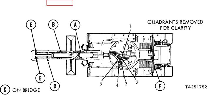
OVERHEAD CYLINDER. This cylinder is actuated by lever (1) which will shut off or
(A)
allow pressure to flow to either the cap end (lever up) or the rod end (lever down) of this
cylinder.
TONGUE CYLINDER. This cylinder is actuated by lever (2) which will shut off or allow
(B)
pressure to flow to either the cap end (lever up) or the rod end (lever down) of the
cylinder.
SCISSORS CYLINDER. This cylinder (not illustrated, is on bridge) is actuated by lever (3)
(C)
which will shut off or allow pressure to flow to either the rod end (lever UP) or the cap end
(lever down) of the cylinder.
LOCKING CYLINDER. This cylinder is actuated by lever (4) which will shut off or allow
(D)
pressure to flow to either the rod end (lever up) or the cap end (lever down) of the
cylinder.
EJECTION CYLINDERS. These cylinder are activated by lever (5), (for these cylinders to
(E)
operate lever (4) must be held in the up position) which will allow pressure to flow to the
cap end (lever up) or the rod end (lever down) of the cylinders.
HOLDDOWN CYLINDER. This cylinder is actuated by overhead cylinder level (1) which
(F)
will shut off or allow pressure to flow to either the rod end (lever up) or the cap end (lever
down) of the cylinder.
1-3/(1-4 blank)

