
TM 5-5420-228-24
PUMP-CLUTCH SUPPORT REPLACEMENT (Sheet 1 Of 1)
TOOLS: 9/16 in. socket with 1/2 in. drive
Ratchet with 1/2 in. drive
1/4 in. drive pin punch
3/4 in. socket with 1/2 in. drive
10 in. extension with 1/2 in. drive
Hammer
SUPPLIES:
Lockwashers (8 required)
Lockwashers (4 required)
Remove pump (page 4-29)
PRELIMINARY PROCEDURES:
Remove clutch controls (page 4-27)
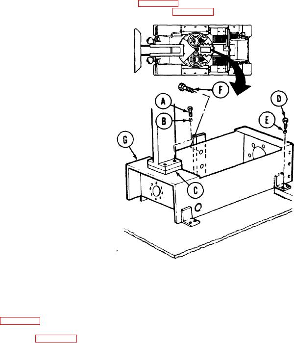
REMOVAL:
Using 9/16 inch socket, remove four
1.
screws (A) and lockwashers (B).
Throw lockwashers (B) away.
tap out
and hammer,
2.
Using punch
spacer (C).
Using 9/16 inch socket and extension)
3.
remove eight screws (D) and lock-
washers (E). Throw lockwashers (E) away.
4.
Using 3/4 inch socket, remove two
screws (F).
5.
Remove pump-clutch support (G).
INSTALLATION:
1.
Place pump-clutch support (G) in position in
vehicle.
2.
Using 3/4 inch socket, install two screws (F).
3.
Using 9/16 inch socket, install eight screws (D) and lockwashers (E).
4.
Using hammer and punch, tap spacer (C) into place.
5.
Using 9/16 inch socket, install four screws (A) and lockwashers (B).
6.
Install pump (page 4-30).
7.
h-stall clutch controls (page 4-28).
TA251683
End of Task
4-32

