
TM 5-5420-202-20-2
ENGINE ACCESS COVERS (RIGHT BANK) REPLACEMENT (Sheet 5 of 5)
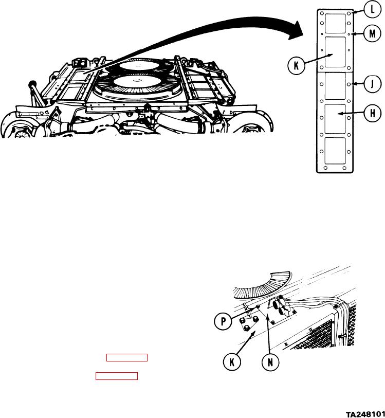
Position rear engine access cover (H) in place on engine.
9.
10.
Install 12 screws and washers (J). Do not install screws in last holes toward front of
engine. Using socket, tighten 12 screws (J).
Position front engine access cover (K) in place on engine.
11.
12.
Install six screws and washers (L). Do not install screw in the four holes (M). Using
socket, tighten six screws (L).
13.
Position plate with electrical connector (N)
on front engine access cover (K). Aline
screw holes in plate (N) with those in front
engine access plate (K).
14.
Install four screws and washers (P) to secure
plate to cover (K). Using socket, tighten four
screws (P).
Install engine shroud (page 9-31).
15.
16.
Install powerplant (page 5-14).
End of Task
6-111