
TM 5-5420-202-20-2
POWERPLANT RIGHT BANK OIL COOLER FRAME AND BRACKETS REPLACEMENT (Sheet 4 of 9)
NOTE
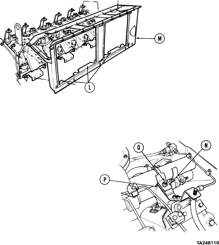
It may be necessary to depress three flanges (L) on frame
bottom during removal to clear protruding obstacles on the
engine.
10. Remove oil cooler support frame (M).
NOTE
Five of the six cooler frame upper brackets are identical and are
mounted the same way. The sixth bracket (N) is located closest
to the engine flywheel end and requires three shims (P) and an
additional screw and self-locking nut (Q) for proper installation.
11.
Using 9/16 inch socket with extension, remove
nut (Q) securing shims (P). Hold screw head
below shims with 9/16 inch wrench to keep
screw from turning.
Go on to Sheet 5
6-120