
TM 5-5420-202-20-2
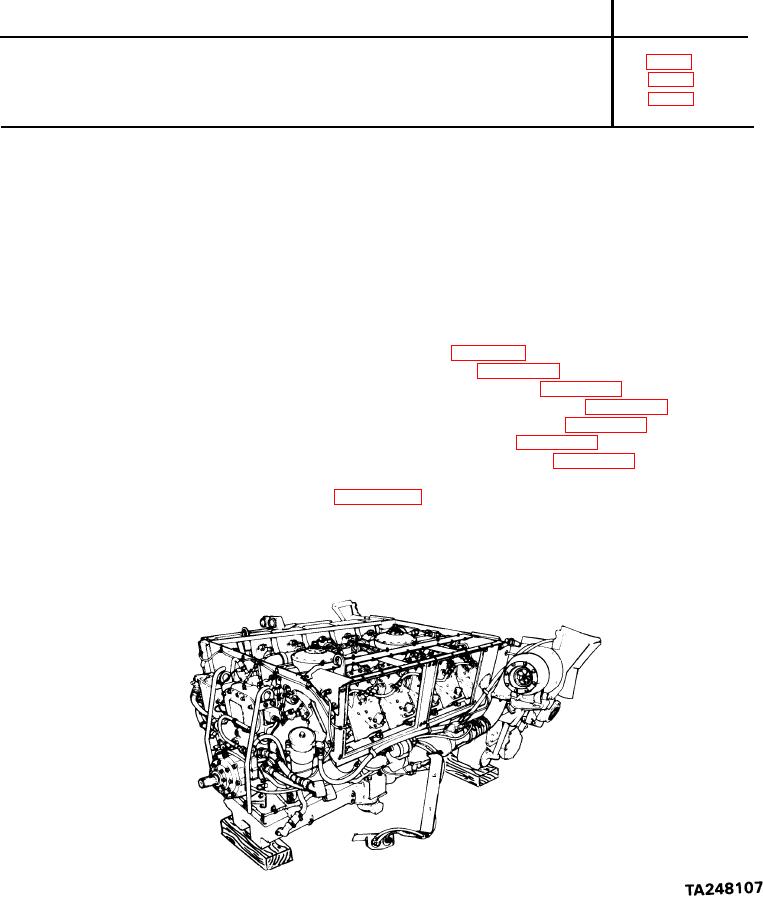
POWER PLANT RIGHT BANK OIL COOLER FRAME AND BRACKETS REPLACEMENT (Sheet 1 of 9)
PROCEDURE INDEX
PAGE
PROCEDURE
Removal
Inspection
Installation
1/2 in. combination box and open end wrench
TOOLS: Ratchet with 1/2 in. drive
9/16 in. combination box and open end wrench
6 in. extension with 1/2 in. drive
11/16 in. socket with 1/2 in. drive
1/2 in. socket with 1/2 in. drive
9/16 in. socket with 1/2 in. drive
Alining punch
Shims
SUPPLIES:
Self-locking
nuts
Two
PERSONNEL:
Remove powerplant (page 5-2)
PRELIMINARY
PROCEDURES:
Remove engine shroud (page 9-30
Remove engine right oil cooler (page 6-19)
Remove transmission right oil cooler (page 6-38)
Remove engine cooling fan shroud (page 9-47)
Remove engine cooling fans (page 9-55)
Remove centrifugal fan housings (page 9-64)
Remove access covers (right bank)
hose (page 10-14)
Go on to Sheet 2