
TM 5-5420-202 -20-2
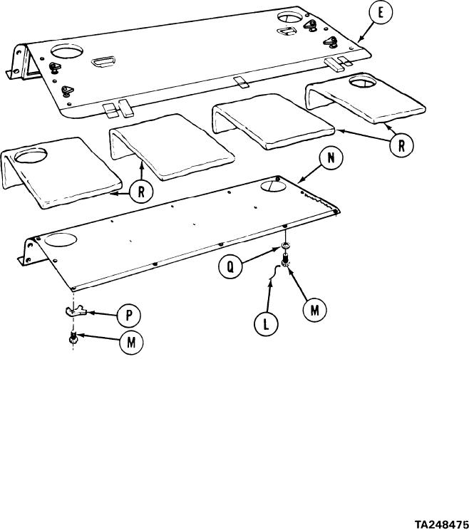
TRANSMISSION SHROUD REPAIR (Sheet 3 of 6)
6.
Using diagonal cutting pliers, remove lockwire (L) from 21 screws (M) on back side of
retainer (N).
7.
Using hammer and chisel, straighten tabs on four key washers (P).
NOTE
Write down location of these four key washers
for use when assembling shroud.
NOTE
If desired, a speed wrench may be used to remove
screws (M).
8.
Using 7/16 inch socket, remove 25 screws (M), 21 flat washers (Q), and four key washers
(P) holding retainer (N) to shroud (E).
Remove retainer (N) from shroud (E).
9.
10.
Remove insulation (R) from shroud (E). Use putty knife as necessary.
Go on to Sheet 4
9-11