
TM 5-5420-202-20-3
DOME LIGHT ASSEMBLY REPAIR (Sheet 8 of 8)
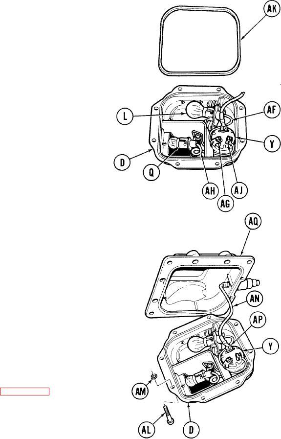
11. Using flat-tip screwdriver, install lead (AF)
from lampholder (L) to connector (AG) which
is marked "W" on switch (Y).
12. Using flat-tip screwdriver, install lead (AH)
from lampholder (Q) to connector (AJ) which
is marked "R" on switch (Y).
13. Using fingers, install door seal (AK) in seal
groove of door (D).
14. Using fingers, install eight screws (AL).
NOTE
If not replacing screws (AL) disregard step 15.
15. Using pliers, install rings (AM) on
screws (AL).
16. Using flat-tip screwdriver, install lead
(AN) on remaining connector (AP) of switch
(Y).
17. Using flat-tip screwdriver, tighten eight
screws (AL) securing door (D) to dome light
(AQ).
18. Install dome light (page 10-192).
End of Task
TA249141
10-200