
TM 5-5420-202-20-3
FUEL TANK CAPACITOR AND HOUSING ASSEMBLY REPLACEMENT (LEFT) (Sheet 1 of 5)
PROCEDURE INDEX
PROCEDURES
PAGE
Removal
Installation
TOOLS:
Flat-tip screwdriver
Slip-joint pliers
1/2 in. socket with 1/2 in. drive
Diagonal cutting pliers
Putty knife
Ratchet with 1/2 in. drive
Torque wrench with 1/2 in. drive (0-175 lb-ft)
Dry cleaning solvent (Item 55, Appendix D)
Gaskets
SUPPLIES:
Lint-free cloth (Item 12, Appendix D)
Gloves (Item 69, Appendix D)
Lockwire (Item 61, Appendix D)
Goggles (Item 70, Appendix D)
Lockwashers (8 required)
REFERENCE:
PRELIMINARY
PROCEDURES:
Remove powerplant (page 5-2).
Drain left fuel tank (TM 5-5420-202-10)
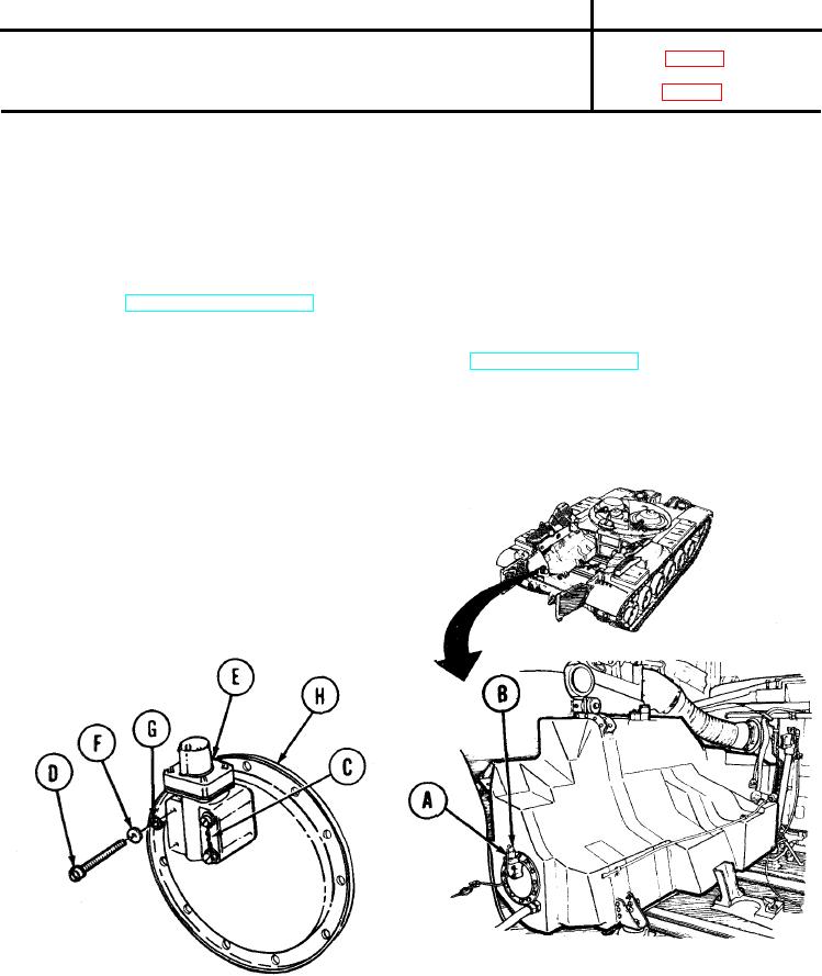
REMOVAL:
1.
Remove electrical connector (A) from capacitor and housing electrical connector (B) by
pulling out.
Using diagonal cutting pliers, remove lockwire (C) securing four screws (D) on capacitor
2.
and housing (E).
Using screwdriver, remove four screws (D),
3.
flat washers (F), and lockwasher (G) from
capacitor and housing (E).
Slowly separate capacitor and housing (E)
4.
from cover (H). Capacitor and housing (E)
are connected to cover (H) with an electrical
lead.
TA249263
Go on to Sheet 2