
TM 5-5420-202-20-3
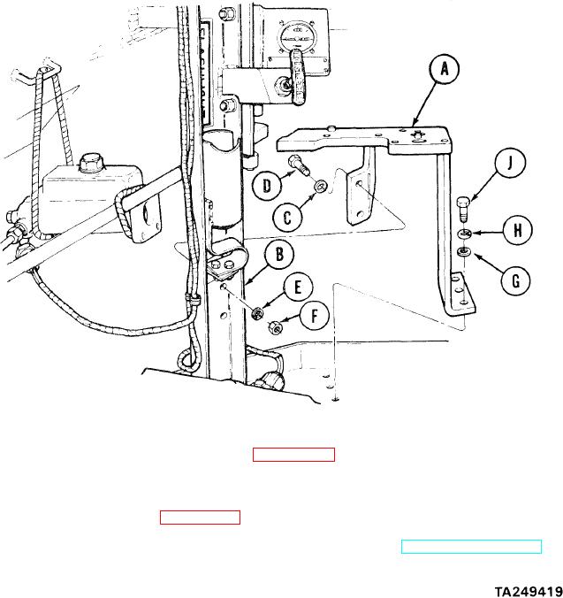
MASTER CYLINDER AND PEDAL LEVER MOUNT ASSEMBLY REPLACEMENT (Sheet 3 of 3)
2.
Inspect the mount (A) for cracks or broken alinement pins. Replace if unserviceable.
INSTALLATION:
1.
Place mount (A) behind column (B) with
holes alined.
Place two washers (C) on screws (D) and
2.
install through rear of mount (A).
3.
Use 9/16 inch wrench to hold screws (D).
Using socket and extension, install two
lockwashers (E) and nuts (F).
Using socket and extension, install three washers (G), lockwashers (H), and screws (J).
4.
Install master brake cylinder mounting bracket (page 13-25).
5.
6.
Remove web straps or rope securing master cylinder.
7.
Install brake foot pedal assembly (page 13-14).
Place shift lever in P (park) position and remove blocks from tracks (TM 5-5420-202-10).
8.
End of Task
13-30